Polarization is an important optical property inherent in all laser beams. Brewster windows, reflective phase retarders, and absorbing thin-film reflectors use the advantage of polarization. On the other hand, it can cause troublesome and sometimes unpredictable results when ignored. Since virtually all laser sources exhibit some degree of polarization, understanding this effect is necessary in order to specify components properly. The following text gives a basic polarization definition and presents the polarization types most commonly encountered.
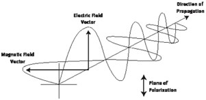
Figure 1 Definition of a polarization vector
Light is a transverse electromagnetic wave; this means that the electric and magnetic field vectors point perpendicular to the direction of wave travel. (Figure 1.) When all the electric field vectors for a given wavetrain lie in a plane, the wave is said to be plane or linearly polarized. The orientation of this plane is the direction of polarization.
Unpolarized light refers to a wave collection which has an equal distribution of electric field orientations for all directions. (Figure 2.) While each individual wavetrain may be linearly polarized, there's no preferred direction of polarization when all the waves are averaged together.
Randomly polarized light is exactly what it says; the light is plane polarized, but the direction is unknown, and may vary with time. Random polarization causes problems in optical systems since some components are polarization sensitive. If the polarization state changes with time, then the components' transmission, reflection, and/or absorption characteristics will also vary with time.
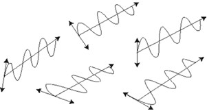
Figure 2 Unpolarized light
Polarization is a vector that has both direction and amplitude. Like any vector, it's defined in an arbitrary coordinate system as the sum of orthogonal components. In Figure 3, we see a plane polarized wave which points at 45° to the axes of our coordinate system. Thus, when described in this coordinate system, it has equal x and y components. If we then introduce a phase difference of 90° (or one-quarter wavelength) between these components, the result is a wave in which the electric field vector has a fixed amplitude but whose direction varies as we move down the wavetrain. (Figure 4.) Such a wave is said to be circularly polarized since the tip of the polarization vector traces out a circle as it passes a fixed point.
If we have two wavetrains with unequal amplitude and with a quarter-wave phase difference, then the result is elliptical polarization. The tip of the polarization vector will trace out an ellipse as the wave passes a fixed point. The ratio of the major to the minor axis is called the ellipticity ratio of the polarization.
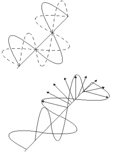
Figure 3 Two Equal Components
Always state the polarization orientation when ordering optical coatings for use at non-normal incidence. If you are unsure about how to determine the polarization state of your source, please contact our applications engineers for assistance.
A wave is resolved into two equal components(Figure 3), each at 45° to the orginal (top). Introducing a quarter-wave phase difference between these components produces a result in a wave whose amplitude is constant (bottom), but whose polarization vector rotates.
When light strikes an optical surface, such as a beamsplitter, at a non-perpendicular angle, the reflection and transmission characteristics depend upon polarization. In this case, the coordinate system we use is defined by the plane containing the input and reflected beams. Light with a polarization vector lying in this plane is called p-polarized, and light, which is polarized perpendicular to this plane, is called s-polarized. Any arbitrary state of input polarization can be expressed as a vector sum of these s and p components.
For s-polarization(Figure 4), the input polarization is perpendicular to the plane (shown in color) containing the input and output beams. For p-polarization, the input polarization is parallel to the plane (shown in color) containing the input and output beams.
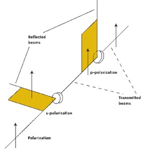
Figure 4 S-Polarization
To understand the significance of s and p polarizations, examine the graph which shows the single surface reflectance as a function of angle of incidence for the s and p components of light at a wavelength of 10.6µm striking a ZnSe surface. Note that while the reflectance of the s component steadily increases with angle, the p component at first decreases to zero at 67° and then increases after that. The angle at which the p reflectance drops to zero is called Brewster's Angle. This effect is exploited in several ways to produce polarizing components or uncoated windows which have no transmission loss such as the Brewster windows.

Request a Consultation
Have questions about how this applies to your application? Contact our experts for a consultation.
